A well-designed quartz slab factory layout should follow the production flow, not simply fit machines into the available space. Raw materials, semi-finished slabs, workers, and handling equipment must move smoothly from preparation and forming through calibration, inspection, storage, and dispatch.
Poorly planned routes can create forklift conflicts, unnecessary waiting, repeated handling, and a higher risk of slab damage. The layout must also provide enough space for utilities, environmental systems, maintenance work, safe access, and future expansion.
Before finalizing any equipment position, the entire workflow should be reviewed against one practical question: can each slab move through every production stage safely and without interruption?
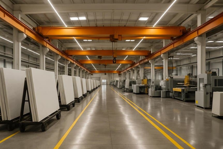
Start every quartz slab factory layout by mapping movement, not by positioning machines. The primary design variable is the controlled transfer of raw materials, mixed compounds, unfinished slabs, finished slabs, workers, forklifts, water, and waste.
A plant may physically contain every required machine yet still lose efficiency when slabs move backward, intersect forklift routes, or wait unnecessarily between stages.
The preferred production workflow should follow one direction: raw material receiving → batching and mixing → slab forming and pressing → curing and cooling → calibration and polishing → cutting and inspection → storage and dispatch.
This sequence reduces handling, shortens travel distance, and improves supervision. Before equipment locations are fixed, planners should verify material paths, slab turning points, buffer needs, and access lanes to maintain predictable throughput.
A quartz slab factory should be divided according to how materials and slabs move through production. Each zone has a different operational purpose, but the four areas must function as one connected workflow.
The preferred sequence is:
Raw material preparation → slab forming and curing → calibration, polishing, and cutting → finished slab storage and dispatch
Keeping these zones in production order reduces backtracking, unnecessary handling, forklift traffic, and work-in-progress congestion. The exact arrangement may be linear, U-shaped, or divided across parallel bays, depending on the building, but the relationship between the zones should remain logical.
Position Zone 1 near the raw-material entrance to minimize internal transport and isolate dusty or liquid-material handling from finished slab movement. This zone should cover quartz sand and powder receiving, raw material storage for bulk silos, bagged materials, resin tanks, pigment, and additive inventory.
The layout should place unloading points directly beside storage, with controlled access, spill containment, dust extraction, and clear forklift aisles.
Weighing and batching should sit between storage and mixing and material preparation equipment, creating a short, traceable route from inventory to process feed.
Separate lanes should prevent overlap with finished slabs, packaging, and dispatch traffic. For tighter control, the factory should assign fixed locations, batch labeling, and inspection points, enabling accurate consumption tracking, stable formulations, and efficient upstream supply to production.
After batching, the production flow should move directly into Zone 2, where prepared materials are distributed to mold or paper preparation, forming, pressing, curing, cooling, and intermediate slab staging.
The layout should keep material distribution aligned with mold handling to reduce cross-movement and maintain cycle discipline.
The pressing and curing area requires clear access for feeding, press operation, slab transfer, maintenance, and emergency intervention.
Equipment spacing should support vacuum, vibration, hydraulic pressing, oven loading, and controlled cooling without interrupting upstream supply.
Capacity balance is critical: a high-speed press matched with insufficient curing volume only transfers the bottleneck downstream.
Temporary buffers should be sized for normal cycle variation, not uncontrolled accumulation.
Intermediate slab staging must remain organized, traceable, and close enough to protect continuous flow.
Arrange Zone 3 as a continuous wet-finishing line that receives cured slabs through slab turning and feeding, then moves them through thickness calibration, polishing, edge trimming, cutting, inspection, and rework without reverse flow.
In a controlled quartz slab production line layout, calibration machines should align directly with the polishing line layout, keeping slab transfer stable and measurable.
Space must be reserved for water supply headers, wet-processing drainage channels, sludge collection pits, abrasive replacement access, and scheduled machine maintenance.
Cutting and edge trimming stations should follow polishing to prevent repeated handling and protect finished surfaces.
Inspection points should be placed after cutting, with a defined rework loop returning only nonconforming slabs to correction stations.
This arrangement improves flow discipline, reduces congestion, and supports predictable finishing capacity.
Once calibration, polishing, cutting, and inspection are completed, finished slabs should move directly into Zone 4 without crossing raw-material routes or upstream production traffic.
This zone controls final inspection, protective film application, product identification, finished slab storage, and loading and dispatch. Each slab should receive clear labeling for order number, size, color, batch, grade, and destination before entering the storage sequence.
A-frame storage should be arranged by order status, delivery priority, and slab type to reduce handling and retrieval time.
Rejected or rework slabs require a separate holding lane, preventing accidental shipment and keeping quality decisions traceable.
The dispatch area should allow safe A-frame turning, forklift movement, container loading, and order preparation. A direct outbound route improves control, protects finished surfaces, and stabilizes shipment scheduling.
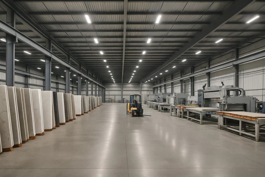
There is no single floor-area figure that applies to every quartz slab factory. The required space depends on the production line configuration, slab size, output target, automation level, storage policy, and the condition of the building itself.
A useful way to assess a site is to calculate the space in layers rather than looking only at the machine footprint.
If you're still in the early planning stage, our guide on starting a quartz stone manufacturing plant covers the complete process—from market positioning and production planning to factory setup and equipment selection.
Begin by placing the major production systems in the correct process sequence:
Raw material preparation → mixing and distribution → pressing → curing and cooling → calibration and polishing → cutting and inspection → storage and dispatch.
This gives you the base equipment area. However, it is only the starting point. A building may appear large enough on paper but still be unsuitable once operating, maintenance, handling, and storage space are added.
If you are determining which machines to include at each production stage, see our complete Quartz Stone Production Line Equipment List.
Each machine needs space around it for normal operation and servicing.
Reserve access for:
This is especially important around the press, curing system, polishing line, pumps, motors, and electrical cabinets. If maintenance access is too limited, even a small repair can require nearby equipment or stored slabs to be moved.
Quartz slabs are large, heavy, and vulnerable to edge damage, so movement space must be planned carefully.
Account for:
Do not calculate aisle width only from the forklift body. The turning radius, slab dimensions, A-frame size, and need for two-way movement may require significantly more space.
A factory also needs space for materials and slabs that are not inside a machine.
Include areas for:
These buffer areas help keep the line running when one production stage operates faster than the next. Without enough staging space, slabs can block aisles, interrupt machine feeding, or create unnecessary handling.
Finished slab storage should be calculated from expected production output and dispatch frequency. A factory shipping daily will need a different storage allowance from one holding several weeks of inventory.
Finally, reserve separate space for the systems that support production.
This may include:
These systems should not be squeezed into leftover corners after the production equipment has been positioned. Their location affects pipe length, drainage, maintenance access, safety, and operating efficiency.
A simple planning formula is:
Required factory space = equipment area + operating clearance + material movement + storage and buffers + utilities and environmental systems
The building should only be considered large enough when all five parts fit together without blocking production flow, maintenance access, loading activities, or future expansion.
The shape and structural conditions of the building have a major influence on how the quartz slab production line should be arranged. A long, narrow factory usually supports a straight production flow, while a wide, open building allows more flexibility for U-shaped or parallel layouts. Existing buildings may require additional compromises because of columns, fixed doors, limited height, drainage points, or restricted equipment access.
The goal is not simply to fit every machine into the available space. The layout should maintain logical slab movement, reduce unnecessary handling, separate raw-material and finished-product traffic, and preserve enough room for operation and maintenance.
A linear layout is usually the most practical choice for a long, narrow building. Raw materials enter at one end of the factory and move through batching, mixing, material distribution, pressing, curing, cooling, polishing, inspection, and packaging before finished slabs leave from the opposite end.
This arrangement creates a clear one-direction production flow and reduces the risk of raw materials, unfinished slabs, and finished products crossing the same routes. It can also simplify production supervision because each process occupies a defined position along the line.
However, the available width must be checked carefully. Space is required not only for the machines, but also for:
If the building is too narrow, the line may fit physically but still create handling bottlenecks. The layout should therefore confirm aisle width, slab-carrier dimensions, turning radius, maintenance clearance, and safe separation between vehicles and workers before equipment positions are finalized.
A wide, open building offers more flexibility for arranging the production line. Depending on the site and logistics requirements, the factory may use a U-shaped flow, parallel production zones, or a combination of linear sections.
A U-shaped layout can place raw-material receiving and finished-slab dispatch on the same side of the building while keeping the production stages connected around the factory. This may shorten internal travel and make supervision easier.
Parallel zones can also work well when the pressing line, curing area, and polishing line need to be positioned side by side. This arrangement can improve access to utilities, maintenance areas, and intermediate slab buffers.
| Layout option | Main advantage | Key consideration |
|---|---|---|
| U-shaped flow | Shorter internal travel and centralized supervision | Raw-material and finished-slab routes must remain separated |
| Parallel production zones | Flexible equipment arrangement and easier expansion | Transfers between zones must remain direct and controlled |
| Same-side receiving and dispatch | Simplified external logistics | Truck and forklift traffic must not interfere with production |
| Separate raw-material route | Lower contamination and traffic risk | Requires clearly defined delivery and storage access |
The main risk in a wide building is creating too many crossing routes. The additional space should be used to improve flow, not to scatter equipment across the factory. Clearly defined lanes, buffer areas, pedestrian routes, and slab-transfer paths help maintain an orderly production sequence.
An existing building should not be approved based on total floor area alone. Structural and access restrictions can have a greater impact on the quartz slab factory layout than the building’s overall size.
Before confirming the layout, check:
Columns may prevent a completely straight production flow, requiring offset conveyors, split production zones, or additional slab-transfer points. Fixed doors may also determine where raw materials enter, where finished slabs are dispatched, and how large equipment can be installed.
In some cases, the press or curing system may need to be repositioned to meet structural loading, ventilation, or maintenance requirements. Intermediate slab buffers can help maintain production stability where direct machine-to-machine transfer is not possible.
A successful layout for an existing building should work with the structure rather than forcing a standard production-line arrangement into unsuitable space. The final design should preserve a logical process sequence while minimizing additional handling, traffic conflicts, and future maintenance difficulties.
A quartz slab factory layout should do more than fit the equipment into the available floor area. It should keep raw material storage, batching, mixing, pressing, curing, polishing, inspection, and finished slab storage connected through a controlled production flow.
The transition between each stage should be checked for three things: whether the downstream equipment can handle the upstream output, whether the transfer distance is practical, and whether enough buffer space is available when production speeds are temporarily unbalanced.
| Production transition | Typical layout problem | Operational result |
|---|---|---|
| Storage to batching | Long or shared delivery route | Slow material feeding and wider dust dispersion |
| Mixing to pressing | Excessive transfer distance or poor coordination | Material delays and inconsistent slab forming |
| Pressing to curing | Insufficient buffer space or curing capacity | Press stoppages and reduced line utilization |
| Curing to polishing | Inadequate cooling or staging area | Slab congestion and delayed finishing |
| Polishing to storage | Narrow slab-handling route | Higher damage risk and slower dispatch |
| Wet processing to treatment | Poor drainage or long wastewater routes | Water accumulation, difficult cleaning, and higher maintenance requirements |
The aim is not to create large amounts of work-in-progress between machines. Instead, the layout should provide enough controlled staging space to absorb short production differences without allowing slabs to accumulate or block the line.
Pressing, curing, and polishing capacities should therefore be planned as one connected system. A high-output press provides little benefit if the curing system, polishing line, or slab-handling route cannot keep pace.
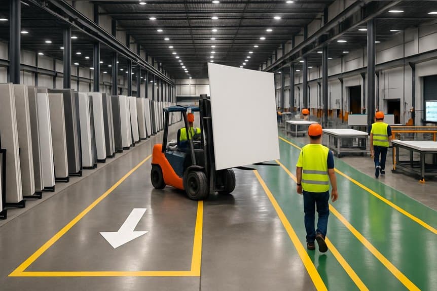
Every movement path in a quartz slab factory should be planned to separate forklifts, workers, slabs, and maintenance access with minimal conflict. In an artificial quartz stone plant layout, controlled routing reduces collisions, edge damage, and handling delay.
Chemical storage should remain outside high-traffic movement corridors.
This disciplined route structure gives managers predictable flow, safer supervision, and better protection for large, heavy, vulnerable slabs during daily production.
Safe routing only works at full efficiency when utilities and environmental systems are placed in direct relationship to the production steps they support. A dust collection system should sit close to quartz powder handling, batching, and mixing points to reduce duct length, pressure loss, and uncontrolled particulate escape.
Ventilation and extraction should align with resin mixing, forming, and curing zones, where emissions require immediate capture.
The wastewater treatment layout should connect directly to calibration, polishing, and cutting operations, with sludge treatment accessible from wet processing and waste-removal routes.
Electrical distribution must remain reachable for control and service while protected from water, dust, and heavy traffic.
Compressed air lines should follow short, maintainable paths.
Maintenance areas should be near core equipment, but outside slab, forklift, and operator movement corridors.
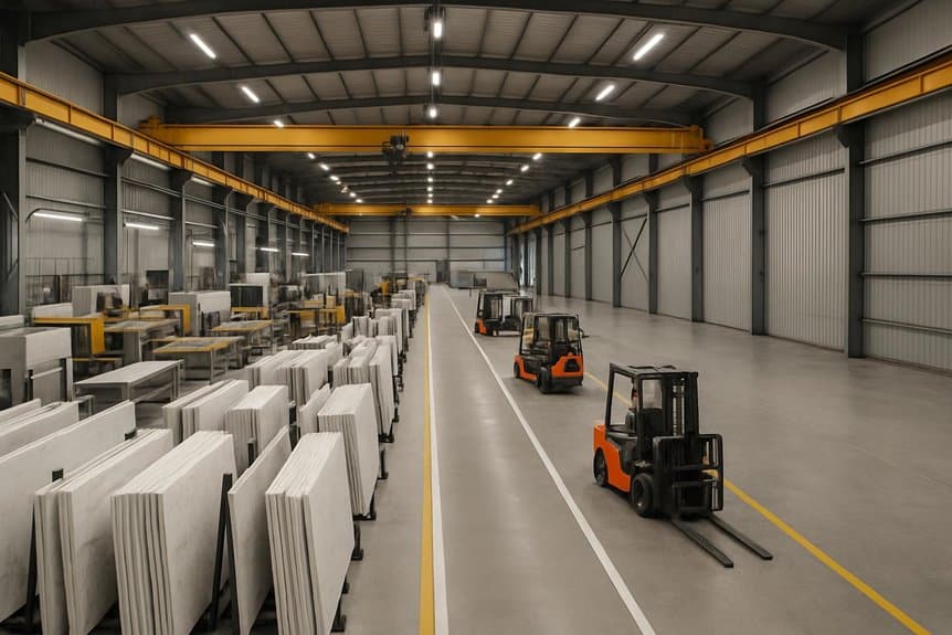
As production demand increases, a quartz slab factory layout should reserve a defined expansion route that connects directly to the existing process flow rather than relying on unused floor space.
In factory expansion planning, each reserved zone should show where added equipment enters the sequence and how output remains controlled.
This approach converts expansion from guesswork into a controlled production pathway with measurable capacity growth.
Planning for future expansion during the initial layout stage can also help reduce modification costs and avoid unnecessary reinvestment.
After the expansion route has been defined, the quartz slab factory layout should undergo a final approval-stage review before foundations, drainage, and utility installation begin.
The review verifies that equipment follows the intended process sequence and that pressing, curing, and polishing capacities remain balanced. It should confirm maintenance access, slab movement clearance, door widths, aisle dimensions, and major equipment replacement paths against quartz stone plant space requirements.
Traffic and material flow require equal control. Forklift and pedestrian routes should not conflict, raw materials and finished slabs should not cross unnecessarily, and loading areas must not obstruct production.
Storage capacity, drainage, dust collection, and wastewater positions should match output and wet-processing demand. The equipment supplier, owner, civil contractor, electrical team, and environmental provider should approve the layout before civil work starts.
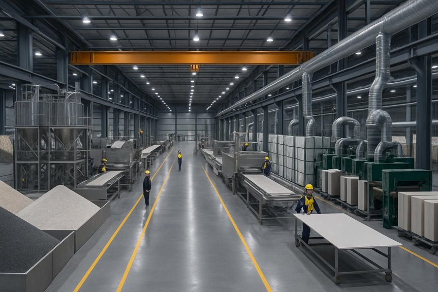
A well-planned quartz slab factory layout should turn production targets and building constraints into one coordinated system for equipment, material flow, storage, traffic, utilities, and environmental control.
SINONE develops project-specific layout plans based on your factory dimensions, target slab formats, required output, automation level, equipment configuration, storage needs, utility conditions, and local environmental requirements. The aim is to create a clear production path from batching and mixing through pressing, curing, polishing, inspection, and finished-slab handling, while reducing unnecessary movement and production bottlenecks.
During layout planning, SINONE can help you:
For a preliminary layout assessment, send SINONE your factory drawing, target slab dimensions, expected production capacity, preferred automation level, and destination market.
A new quartz slab factory should target 200,000–500,000 m²/year initially. Like a calibrated press, capacity should match orders, lot size, design mix, automation level, and quality targets, then scale toward market demand predictably.
Veins, multicolors, special designs, and elongated vein patterns require Matrix pigment spraying, StatuTikar CNC veining, CNC texture drawing, or thermal transfer systems. Solid colors and basic blends typically run on standard automated quartz slab production lines.
Like a cockpit crew, an automated quartz slab line typically needs minimal operators: mainly monitors for batching, pressing, curing, polishing, inspection, and maintenance. Exact staffing depends on automation level, capacity, product complexity, and quality-control requirements.
Factories should enforce standards for density, flatness, color consistency, curing strength, surface finish, dimensions, and defect rates. Controls should monitor pressure, temperature, viscosity, batching accuracy, polishing quality, inspection records, traceability, repeatability, and equipment stability.
Installation and commissioning usually take 60–120 days; particularly, automated lines can cut labor by about 40%. Duration depends on equipment scope, civil readiness, utilities, automation level, trial production, operator training, and acceptance testing.



[…] raw-material preparation, moulding and forming, curing, finishing equipment, automation software, plant layout, installation, start-up support, process know-how, and operator […]